


1. Introduction
Fire resistance of Reinforced Concrete (RC) columns is important to ensure the overall safety of structures when a fire occurs. When RC columns are exposed to fire, their capacities are significantly reduced. In addition, the surface of column can partially be exposed to fire depending on fire condition and floor plan, which cause asymmetric behaviors of fire-damaged columns.
There have been many experimental and numerical studies on the behavior of columns under fire conditions. The paper by Tan and Yao (2003) developed a simple and rational method to predict the fire resistance of RC columns subjected to four-face heating. Both uniaxial and biaxial bending of columns was considered. In the paper by Mao and Kodur (2011), an experimental study were constructed to study Concrete Encased Steel (CES) columns under standard fire exposure conditions were presented. The test parameters include column size, 3- and 4-side fire exposure, load intensity and load eccentricity. Buch and Sharma (2019) tested to determine the influence of relative levels of spalling under eccentric loads on fire resistance of RC columns. Interaction diagram is useful index for design and evaluating the capacity of fire-damaged columns. Caldas et al. (2010) presented a procedure to obtain interaction diagrams of RC sections of general shape subjected to fire action. Kim (2008) studied spalling, temperature distribution of interior column, residual strength and movement of column in eccentric loading with expose time of high temperature. And P-M interaction diagram was made according to various column section using nonlinear analyses. El-Fitiany and Youssef (2014) constructed interaction diagrams for heated RC columns using practical approach. In addition, this paper presents the derivation of a set of formulas that can be used to estimate the average temperature distribution within the concrete section and the corresponding internal forces. Law and Gillie (2010) reported a new method of creating two- or three-dimensional interaction diagrams under any temperature field based on the tangent stiffness matrix of a section. Among many related researches, effect of heated areas on the structural behaviors of fire-damaged columns for the consideration of real fire situation has been studied limitedly. Moreover, P-M interaction diagram of the fire-damaged concrete columns with various heat exposure areas has not been developed.
Therefore, this study aimed to develop modeling method and provide interaction diagrams of fire-damaged RC columns with consideration of various heat exposure areas. Toward the goal, Finite Element (FE) analyses with a simplified section method were performed and the analytical results were compared with experimental results for validation. Then, P-M interaction diagrams of fire-damaged RC columns with various heat exposure areas were established using the proposed modeling method.
2. Analytical Approach and Validation
2.1 Analytical Approach
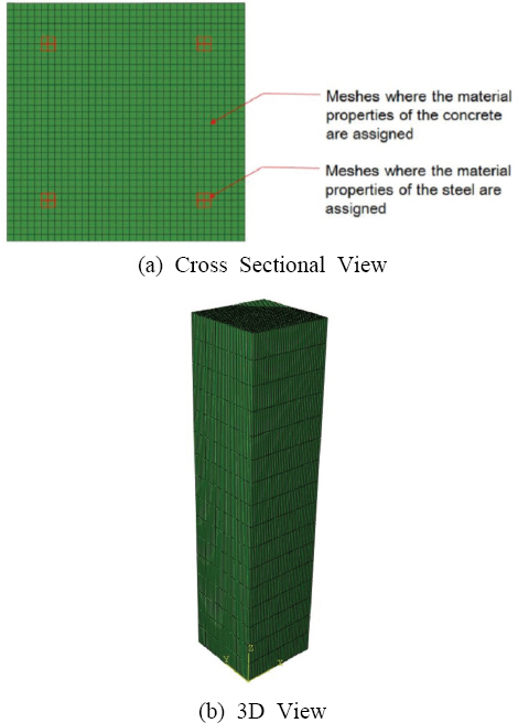
Test specimens were heated for two hours and then were cooled for one week. Axial loading tests were performed to measure the residual strength of the fire-damaged columns with same condition as analyses. The details of experimental methods can be found from the paper (Ryu, 2020). A total of five models having different heat exposure areas of none to four side surfaces were modeled using ABAQUS 6.3-10 (Dassault Systèms, 2013) as listed in Table 1. The FE models were generated with eight-node solid elements, having width, depth and height equal to 350, 350, and 1,500 mm, respectively. These dimensions were determined to be same as test specimens for the validation with experiments (Ryu, 2020). Elements for the reinforcing steel bars were included in the model by assigning steel material properties to the meshes where the steel bars were located, as illustrated in Fig. 1. Rest of the elements were modeled with concrete material properties.
Table 1
List of Models
| No. | Model Name | Heated Surface |
|---|---|---|
| 1 | C0 | None |
| 2 | H1 | One side surface |
| 3 | H2 | Two side surfaces |
| 4 | H3 | Three side surfaces |
| 5 | H4 | Four side surfaces |
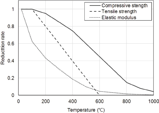
For the thermal analyses, elevated temperatures were applied to the designated surfaces according to ISO 834 (1999) standard time-temperature curve, while initial temperature was given as room temperature to all nodes on the surfaces. During the analyses, time increment was controlled automatically with ranges from 0.001 to 100 sec. The temperature dependent thermal and mechanical properties such as effective specific heats, conductivities, the elastic modulus, the compressive and tensile strengths for the concrete and steel referred to Eurocode 2 (EN 1992-1-2, 2004) and included in the models. The values of those for the concrete and steel with the increasing temperature are illustrated in Fig. 2.
From the thermal analyses, temperature distributions inside the column were obtained, which could determine mechanical material properties of fire-damaged concrete and steel for the structural analyses.
For the structural analyses of the fire-damaged columns, two different modeling methods were used; original section method and simplified section method as shown in Fig. 3. Original section method was to assign temperature dependent mechanical material properties of concrete and steels according to the temperature distributions obtained from the thermal analyses. Therefore, relatively low stress-strain curve of the concrete was assigned to the elements near heated surface while the stress-strain curve of the concrete at room temperature was assigned to the elements near unheated area. In the simplified section method, the part exposed to temperatures above 500 °C or 700 °C was considered extremely damaged and excluded from the model. Then, the remained part was modeled with material properties at room temperature. In this manner, the less number of elements was required compared to the case of original section method, and material properties only at room temperature was needed. For the validation, the results predicted from the simplified section method were compared with the experimental results. In addition, within the simplified section method, the analytical results based on 700 °C isotherm and 500 °C isotherm were compared each other to determine temperature criteria. The 500 °C isotherm method is referred to Eurocode 2 and generally used to estimate the fire resistance of RC element. For both original section method and simplified section method, concrete damaged plasticity constitutive model was used.

Loading and boundary conditions were prescribed such that the top surface was axially loaded and nodes on the bottom surfaces were fixed.
2.2 Validation
2.2.1 Heat Transfer Analysis
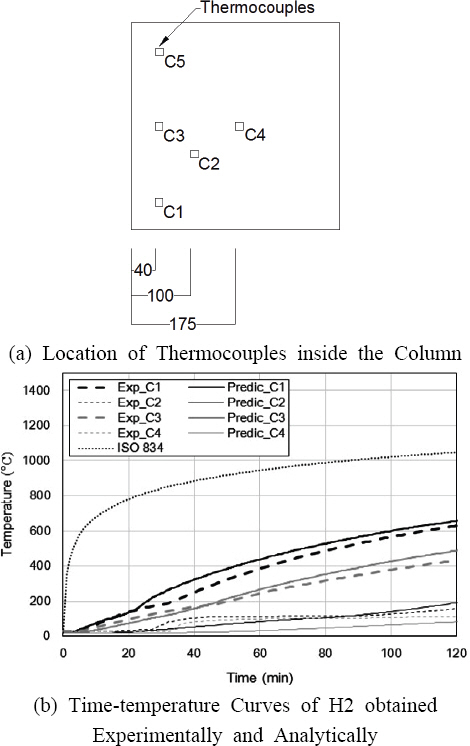
Fig. 4. shows the representative timeвАУtemperature curves of specimen H2 obtained experimentally and analytically. Table 2. shows maximum temperatures of RC columns obtain from experiments and analyses (Ryu, 2020). From the figure, it was found that the temperature distributions of the model predicted by the heat transfer analyses were in good agreement with experimental results. The differences between the experimental and analytical results of temperature distributions were within 50 ¬ЇC for all the models from H1 to H4. Therefore, the temperature distributions obtained from the thermal analyses may be used to model fire-damaged RC columns for structural analyses.
2.2.2 Structural Analysis
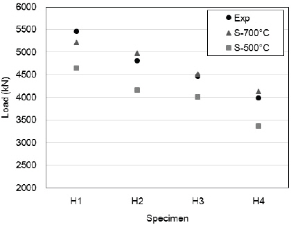
In order to validate the simplified section method, the analytical results of maximum loads were compared with experimental results as shown in Fig. 5. In addition, to determine temperature criteria for the simplified section method, predicted results based on 700 °C isotherm (the proposed isotherm) and 500 °C isotherm (following Eurocode 2) were compared each others. The differences of maximum loads between the experimental and analytical results were significantly large as 10~16% when the analytical method used 500 °C isotherm. On the other hand, the maximum loads obtained analytically based on 700 °C isotherm were similar to those of specimens obtained from experiments. The differences of maximum loads of columns between the experimental results and analytical results based on 700 °C isotherm were within 5%. It can be found that the 500 °C isotherm method suggested to Eurocode 2 is conservative to estimate the structural behavior of fire-damaged column because analytical results obtained from 500 °C isotherm method were considerably lower than experimental results. However, in this study, the results obtained from simplified section method with 700 isotherm were found to be closer to the experimental results, compared to those obtained from simplified section method with 500 isotherm.
3. P-M Interaction Diagram of Fire-damaged Column
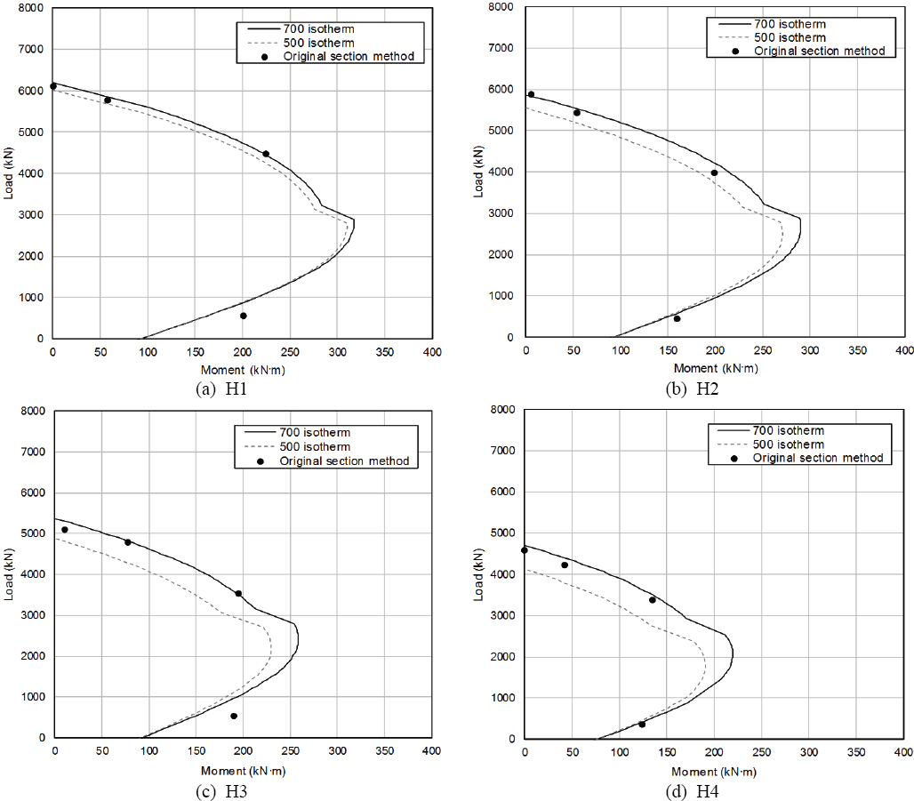
To estimate the load capacity of fire-damaged column, the P-M interaction diagrams obtained using Eqs. (1) and (2) were plotted as solid and dashed lines of Figs. 6(a)~(d). These diagrams considered simplified section based on 500 °C and 700 °C isotherm. Once values were obtained at several points, the P-M interaction diagram of the fire-damaged column was plotted by linking between the points. In addition, results obtained from the FE analysis using the original section method were plotted together with the P-M interaction diagrams for validation.
where, fc = Compressive strength of concrete (MPa)
a= Depth of equivalent rectangular stress block (mm)
b= Width of column (mm)
As = Area of compression reinforcement (mm2)
AвА≤s = Area of tension reinforcement (mm2)
∆Тs = Stress in tension steel (MPa)
∆ТвА≤s = Stress in compression steel (MPa)
Figs. 6(a)~(d) show P-M interaction diagrams of the fire-damaged columns in addition with the analytical results obtained using the original section method. The difference of P-M interaction diagrams of the columns obtained from the simplified section method based on 700 °C isotherm and 500 °C isotherm were 3~13%. When compared with the analytical results obtained using the original section methods, the P-M interaction diagrams from the simplified section method based on 700 °C isotherm matched better than the case of 500 °C isotherm. Therefore, the P-M interaction diagram using the simplified section method based on 700 °C isotherm can be used to predict the strength and moment at various heated area.
4. Conclusions
In this paper, analytical method of simplified section method was proposed and validated. From the validated method, P-M interaction diagrams of the fire-damaged RC columns having different heated areas were generated. The following conclusions can be drawn from the results.
(1) From axial loading test results, the residual strength of the columns decreased as the heated area increased.
(2) The reduced section method by removing part over 700 °C could capture structural behaviors of fire-damaged columns accurately, rather than the reduced section method with 500 °C isotherm.
(3) The predictions of the proposed P-M interaction diagram using the reduced section method were in good agreement with analytical results obtained from original section method.
(4) The proposed P-M interaction diagram using the reduced section can be used to predict the strength and moment at various heated areas.
(5) The further studies are needed to investigate P-M interaction diagram including various cross-sectional size and fire exposure times exposed to fire for the fire-damaged RC columns.


