시뮬레이션을 이용한 비차열 덕트 내화충전구조의 적용 가능성에 관한 연구
Study on the Application Possibility of Uninsulated Duct Firestop System using Simulation
Article information
Abstract
화재 시 비차열 덕트 내화충전구조의 주위로의 복사열 전달 및 영향을 분석하여 건축물에의 적용 가능성을 검토하고자 시뮬레이션을 수행하였다. 시뮬레이션 대상은 바닥 및 벽체 사각 덕트 내화충전구조로서 차열재(1 m 길이) 적용 유무에 따라 구분하였으며, 중요한 입력 데이터인 표면온도는 기존 성능검증 실험 데이터를 활용하였고, 가상 공간을 설정하여 주위 공기온도, 주위 구조체 표면온도 및 덕트로부터 일정 이격 거리에서의 복사온도를 분석하였다. 시뮬레이션 결과, 비차열 덕트 내화충전구조에 차열재를 설치한 경우 복사온도가 현격히 감소하는 등 복사열에 의한 화재확산 가능성을 상당히 줄일 수 있어 건축물에 적용 가능할 것으로 판단되었다.
Trans Abstract
A simulation of the uninsulated duct firestop system was performed to review its application possibility to the building by analyzing the radiant heat transfer and its impact to the surrounding structures in the event of a fire. The simulation targets were divided by the presence or absence of an insulation material (1 m long) as floor and wall duct firestop systems, and the surface temperature, which is an important input data, was based on the existing verification test data. Then, the ambient air temperature, surrounding structure surface temperature, and radiant temperature at some distance from the duct were analyzed through simulations in the modeled virtual spaces. As a result of simulation, it is judged that the application of the uninsulated duct firestop system wrapped by the insulation material can significantly reduce the possibility of fire spreading due to the radiant heat.
1. 서 론
내화충전구조는 방화구획을 형성하는 벽 및 바닥에 형성되는 개구부를 다양한 재질 및 형태의 재료로 충전한 것으로서 방화구획의 내화성능이 유지되도록 한다. 내화충전구조는 개구부(지지구조 포함) 및 개구부를 관통하는 관통재(파이프, 케이블, 덕트 등)에 따라 다양한 공법이 적용되어 현장에 시공된다.
우리나라의 경우, 「건축물의 피난⋅방화구조 등의 기준에 관한 규칙」 제14조제2항제2호에서 내화충전구조 적용과 관련한 내용이 기술되어 있으며, Table 1과 같이 적용내용이 변경되어 왔다(MOLIT, 2019a). 한편, 내화충전구조의 성능 인정 및 현장 적용과 관련하여서는 국토교통부고시 ‘내화구조의 인정 및 관리기준’(MOLIT, 2019b) 및 하위 지침인 ‘내화충전구조 세부운영지침’(MOLIT, 2016)을 통해 현장에 적용할 각 구조에 대한 성능 인정을 수행하고, 현장 적용을 위한 기준을 규정하고 있다.
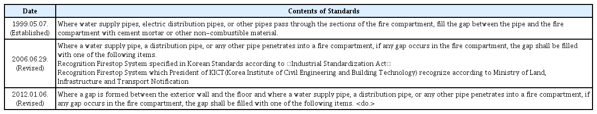
History of Application Standards of Firestop Systems
그러나, 선진 외국에 비해 내화충전구조의 적용과 관련하여 합리적인 현장 적용을 위한 실증적⋅체계적인 연구가 미흡한 실정으로 이에 대한 연구를 진행하여 합리적으로 제도를 개선하는 것이 매우 필요하다.
비차열 덕트 내화충전구조의 적용 가능성에 대한 국내 선행연구로 Lee et al. (2019)는 바닥 비차열 덕트 내화충전구조에 대한 검증실험을 수행하였으며, Seo (2020)는 벽체 비차열 덕트 내화충전구조에 대한 검증실험을 수행하였다.
본 연구에서는 화재 시 비차열 덕트 내화충전구조의 주위로의 복사열 전달 및 영향을 분석하여 건축물로의 적용 가능성을 검토하고자 시뮬레이션을 수행하였다. 시뮬레이션 대상은 바닥 및 벽체 덕트 내화충전구조로서 형태(사각, 원형) 및 차열재(1 m 길이) 적용 유무에 따라 구분하였으며, 중요한 입력 데이터인 표면온도는 기존 성능검증 실험 데이터(Lee et al., 2019; Seo, 2020)를 활용하였고, 가상 공간을 설정하여 주위 공기온도, 주위 구조체 표면온도 및 덕트로부터 일정 이격 거리에서의 복사온도를 분석하였다.
2. 내화충전구조 개요
2.1 내화충전구조의 적용 범위
Fig. 1과 같이 파이프, 덕트, 케이블, 케이블트레이 등의 관통재가 벽체 및 바닥을 관통하는 것은 설비관통부로 구분하며, 벽체와 벽체 사이, 바닥과 바닥 사이 및 바닥과 벽체 사이의 개구부는 선형조인트로 구분하고, 바닥과 외벽 사이의 개구부 및 벽체와 외벽 사이의 개구부는 커튼월 선형조인트로 구분한다. 내화충전구조가 설치되는 지지구조는 콘크리트 바닥, 콘크리트블록 벽체, 건식 벽체(석고보드 간막이벽) 등으로 다양하다.

Application of Firestop System in the Building
2.2 내화충전구조의 요구 성능
Table 2는 국내⋅외 관련제도에서 설비관통부분에 요구하는 내화충전구조의 성능을 비교하여 나타낸 것이다. 일본의 경우 최대 60분의 차염성능을 인정받아 내화충전구조가 적용되도록 하고 있으며, 미국의 경우 수직부재를 관통하는 설비관통부 및 수평 부재를 관통하면서 관통재가 벽에 둘러 쌓여 있고 가연물과 직접적인 접촉이 없는 설비관통부 등에는 비차열(F급) 내화충전구조를 적용토록 하고 있고, 호주의 경우도 100 ㎜ 안에 가연재료가 없거나 출입구 근처에 관통재가 설치되지 않은 경우 비차열(F급) 내화충전구조를 적용토록 하고 있다. 그러나, 국내의 경우 선형조인트 너비가 30 ㎜ 이하인 일반 선형조인트 내화충전구조의 경우에만 비차열(F급) 내화충전구조의 적용이 가능하고, 나머지는 차열성능 까지를 만족하여야 하는 차열(T급) 내화충전구조를 적용토록 함으로써 내화충전구조의 현장 적용과 관련하여 경제적인 손실 및 공법 적용의 비현실성 등의 심각한 문제를 안고 있다. 차열성능의 만족을 위해서 별도의 내화대책이 필요한데 건축물의 종류, 중요도, 관통재의 종류 및 크기와 상관없이 일률적으로 차열성능을 확보토록 하는 것은 지나친 규제에 해당된다.
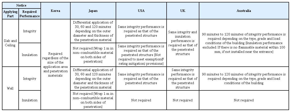
Comparison of the Domestic and Overseas Related Systems for Service Penetrations
3. 시뮬레이션
비차열 사각 덕트 내화충전구조에 대하여 바닥 내화충전구조 및 벽체 내화충전구조로 구분하여 시뮬레이션을 수행하였다.
3.1 소프트웨어
미국 NIST에서 개발한 전산유체역학 시뮬레이션 소프트웨어인 FDS 6.7.3 (NIST, 2019a) 및 Smoke View 6.7.10 (NIST, 2019b)을 사용하였다.
3.2 바닥 내화충전구조
3.2.1 모델링
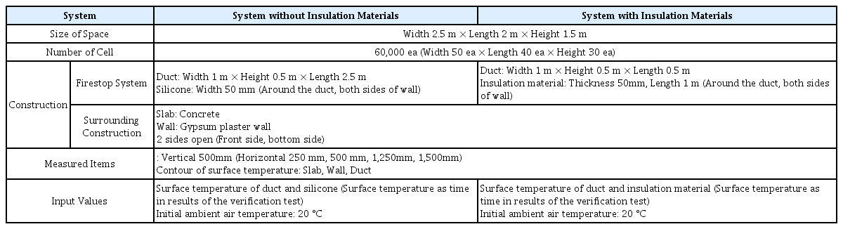
Fig. 2의 Lee et al. (2019) 연구에서의 성능실험 실험체와 동일한 구성으로 Table 3과 같이 공간 및 입력 변수를 설정하여 Fig. 3과 같이 차열재 미적용 바닥 사각 덕트 관통부 내화충전구조 및 차열재 적용 바닥 사각 덕트 관통부 내화충전구조에 대하여 모델링을 하였다.

View of Test Specimens in the Prior Researches
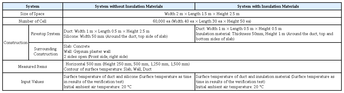
Spaces and Input Parameter in Modelling for Floor Firestop Systems
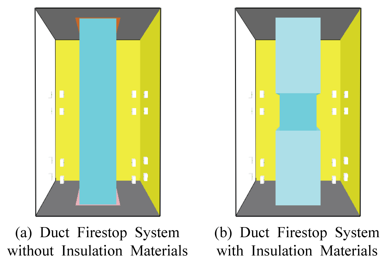
View of Modeling
Fig. 4는 모델링에서 입력값으로 사용한 덕트, 실리콘 및 차열재의 시간에 따른 표면온도를 나타낸 것으로 성능실험 결과에서 측정된 값을 바탕으로 측정위치를 고려하여 표면온도를 선정하였다.

Surface Temperature as Time
3.2.2 시뮬레이션 결과
3.2.2.1 차열재 미적용 바닥 덕트 내화충전구조
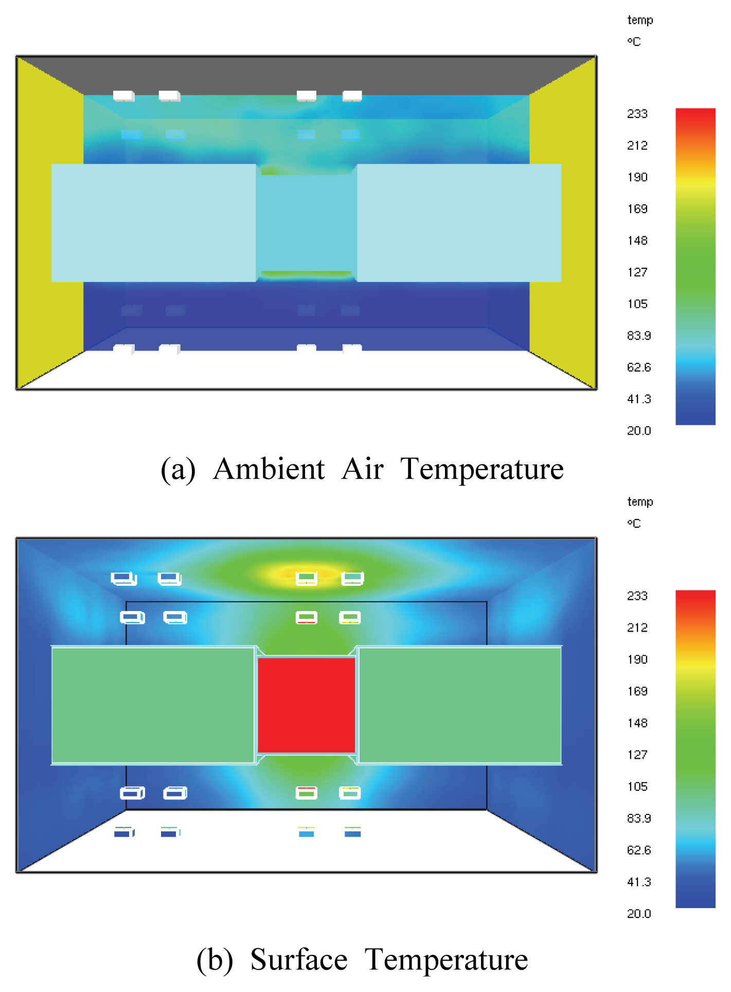
Fig. 5와 같이 차열재 미적용 바닥 덕트 내화충전구조에 대한 시뮬레이션 결과, 2시간 경과시 주위 공기온도는 벽체와 상부 슬래브가 만나는 모서리 부분(점선 표시 부분)에서 100 ℃ 이내를 나타내는 것을 확인할 수 있었으며, 주위구조체 표면온도의 경우 종이의 착화점인 233 ℃를 초과하는 부분이 상당 부분 관찰되었다. 한편, Fig. 6은 각 측정점에서의 시간에 따른 복사온도를 나타내고 있는데, 2시간 경과시 덕트로부터 250 ㎜ 이격된 위치에서의 복사온도는 270 ℃ 내외로 측정이 되었고, 덕트로부터 500 ㎜ 이격된 위치에서의 복사온도는 220∼240 ℃ 정도로 측정이 되었으며, 상대적으로 벽체 쪽에 설치된 측정점에서 복사온도가 높게 나타났다.

Result of Simulations of System without Insulation Materials (Elapsed 2 hours)
Radiant Temperature as Time of System without Insulation Materials
3.2.2.2 차열재 적용 바닥 덕트 내화충전구조
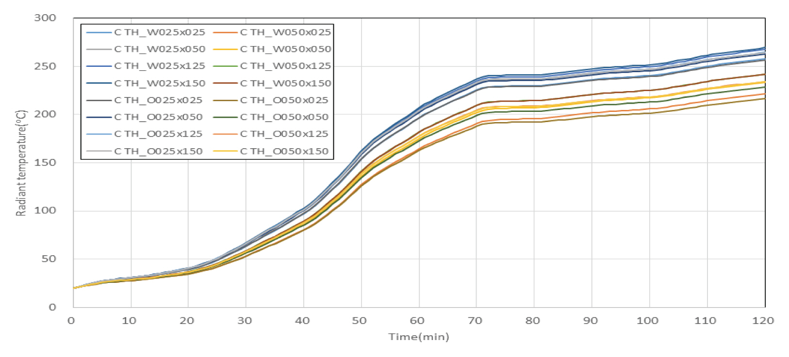
Fig. 7과 같이 차열재 적용 바닥 덕트 내화충전구조에 대한 시뮬레이션 결과, 2시간 경과시 주위 공기온도는 벽체와 상부 슬래브가 만나는 모서리 부분(점선 표시 부분)에서 60 ℃ 이내를 나타내는 것을 확인할 수 있었으며, 주위구조체 표면온도의 경우 종이의 착화점인 233 ℃를 초과하는 부분이 없는 것으로 관찰되었다. 한편, Fig. 8은 각 측정점에서의 시간에 따른 복사온도를 나타내고 있는데, 2시간 경과시 차열재가 적용되지 않은 부분의 덕트로부터 250 ㎜ 이격된 위치에서의 복사온도는 230 ℃ 내외로 측정이 되었고, 덕트로부터 500 ㎜ 이격된 위치에서의 복사온도는 175 ℃ 내외로 측정이 되었으며, 차열재가 적용된 부분의 덕트로부터 250 ㎜, 500 ㎜ 이격된 위치에서의 복사온도는 40∼60 ℃ 정도로 낮게 나타났다.

Result of Simulations of System with Insulation Materials (Elapsed 2 hours)
Radiant Temperature as Time of System with Insulation Materials
3.3 벽체 내화충전구조
3.3.1 모델링
Fig. 9의 Seo (2020) 연구에서의 성능실험 실험체와 동일한 구성으로 Table 4와 같이 공간 및 입력 변수를 설정하여 Fig. 10과 같이 차열재 미적용 벽체 사각 덕트 관통부 내화충전구조 및 차열재 적용 벽체 사각 덕트 관통부 내화충전구조에 대하여 모델링을 하였다.

View of Test Specimens in the Prior Researches
Spaces and Input Parameter in Modelling for Wall Firestop Systems

View of Modeling
Fig. 11은 모델링에서 입력값으로 사용한 덕트, 실리콘 및 차열재의 시간에 따른 표면온도를 나타낸 것으로 성능실험 결과에서 측정된 값을 바탕으로 측정위치를 고려하여 표면온도를 선정하였다.

Surface Temperature as Time
3.3.2 시뮬레이션 결과
3.3.2.1 차열재 미적용 벽체 덕트 내화충전구조
Fig. 12와 같이 차열재 미적용 벽체 덕트 내화충전구조에 대한 시뮬레이션 결과, 2시간 경과시 주위 공기온도는 벽체와 상부 슬래브가 만나는 모서리 부분에서 200 ℃ 이내를 나타내는 것을 확인할 수 있었으며, 주위구조체 표면온도의 경우 종이의 착화점인 233 ℃를 초과하는 부분이 상당 부분 관찰되었다. 한편, Fig. 13은 각 측정점에서의 시간에 따른 복사온도를 나타내고 있는데, 2시간 경과시 덕트로부터 250 ㎜ 이격된 위치에서의 복사온도는 270 ℃ 내외로 측정이 되었고, 덕트로부터 500 ㎜ 이격된 위치에서의 복사온도는 220∼240 ℃ 정도로 측정이 되었으며, 상대적으로 슬래브 쪽에 설치된 측정점에서 복사온도가 높게 나타났다.

Result of Simulations of System without Insulation Materials (Elapsed 2 hours)

Radiant Temperature as Time of System without Insulation Materials
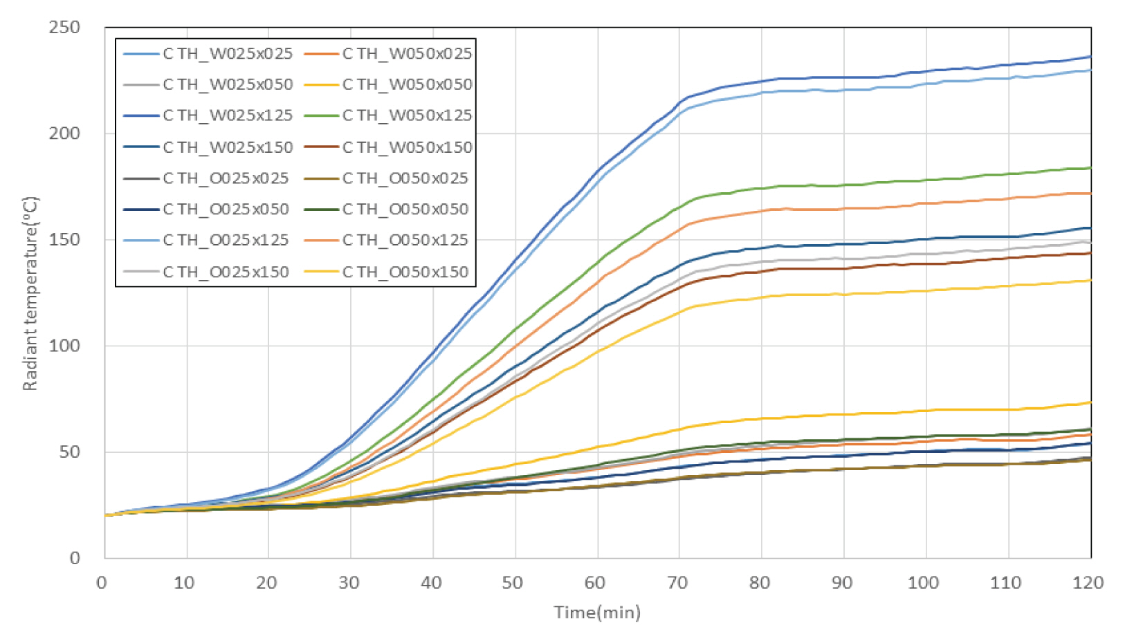
3.3.2.2 차열재 적용 벽체 덕트 내화충전구조
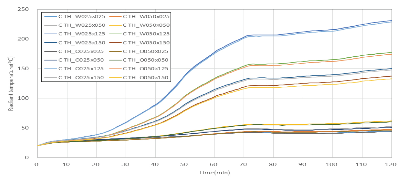
Fig. 14와 같이 차열재 적용 벽체 덕트 내화충전구조에 대한 시뮬레이션 결과, 2시간 경과시 주위 공기온도는 슬래브 하부에서 90 ℃ 이내를 나타내는 것을 확인할 수 있었으며, 주위구조체 표면온도의 경우 종이의 착화점인 233 ℃를 초과하는 부분이 없는 것으로 관찰되었다. 한편, Fig. 15는 각 측정점에서의 시간에 따른 복사온도를 나타내고 있는데, 2시간 경과시 차열재가 적용되지 않은 부분의 덕트로부터 250 ㎜ 이격된 위치에서의 복사온도는 230 ℃ 내외로 측정이 되었고, 덕트로부터 500 ㎜ 이격된 위치에서의 복사온도는 180 ℃ 내외로 측정이 되었으며, 차열재가 적용된 부분의 덕트로부터 250 ㎜, 500 ㎜ 이격된 위치에서의 복사온도는 45∼70 ℃ 정도로 낮게 나타났다.
Result of Simulations of System without Insulation Materials (Elapsed 2 hours)
Radiant Temperature as Time of System with Insulation Materials
4. 결 론
본 연구는 화재 시 비차열 덕트 내화충전구조의 주위로의 복사열 전달 및 영향을 분석하여 건축물에의 적용 가능성을 검토하고자 시뮬레이션을 수행한 것으로 다음의 연구 결과를 도출하였다.
(1) 시뮬레이션을 통해 방화구획을 관통하는 덕트의 비가열면에서 발생하는 복사열로 인한 복사온도가 화재확산의 가능성을 어느 정도 갖는지 평가한 결과, 비차열(F급) 바닥 및 벽체 덕트 내화충전구조에 1 m 길이의 차열재를 설치한 경우 주위 공기온도, 주위구조체 표면온도 및 덕트로부터 일정 이격 거리에서의 복사온도가 차열재를 설치하지 않은 경우와 비교하여 약 70~80% 까지 현격히 감소하는 등 비차열 내화충전구조에 차열재를 설치할 경우 복사열에 의한 화재확산 가능성을 상당히 줄일 수 있을 것으로 판단되었다.
(2) 선진외국의 경우 화재위험성 및 주위 여건에 따라 내화충전구조 성능의 강화 및 완화를 합리적으로 규정하고 있으나 우리나라는 강화 일변도로 규정하고 있어 본 연구와 같은 시뮬레이션 및 성능검증 실험을 통하여 관련 기준을 합리적으로 개선할 필요성이 있는 것으로 판단되었다.
(3) 덕트 내화충전구조의 화재안전성능을 확보하기 위해서는 방화구획을 관통하는 관통재(덕트 등)의 내부에 방화댐퍼를 설치하는 등 구획 부재의 내화성능을 유지할 수 있도록 조치를 하여야 함에도 불구하고 현장에서는 관행적으로 방화댐퍼를 설치하지 않는 등 조치를 하지 않는 경우가 많으므로 이에 대한 확인이 필요하다.
Acknowledgements
본 연구는 2015년 도시건축연구사업과 관련하여 국토교통부의 연구비 지원(과제번호: 20AUDP-B100354-06)에 의해 수행되었습니다. 이에 감사드립니다.