지반침하예방 최적 모니터링 기술 개발을 위한 기술수준 분석
Technical Standard Analysis and Optimal Monitoring Technology to Prevent Ground Subsidence
Article information
Abstract
최근 지반침하 현상이 이슈화되고, 매년 증가함에 따라 정부 및 지자체에서는 지반침하 예방을 위해 여러 가지 대책을 발표하고 있다. 특히, 국토부에서는 주요내용에 ‘불안요소에 대한 선제적 모니터링 및 관리’를 제시하는 등 지반침하 관련 지하시설물 모니터링 기술개발의 중요성이 부각되고 있다. 도심지 지반침하 발생 원인으로 노후 상하수도관로 파손이 가장 크게 지목받고 있으며, 여기에 적용할 수 있는 모니터링기술은 크게 2가지 선제적 및 긴급 대응 기술로 나눌 수 있다. 정확한 관로상태 진단을 위해 관련기술 개발이 국내⋅외에서 활발히 진행되고 있지만 지반침하가 일어날 수 있는 환경과 직접적으로 연계한 기술개발은 이뤄지지 않고 있는 실정이다. 따라서 최근 이슈화되고 있는 도심지 지반침하 예방을 위해 상하수도관로를 계측 및 탐사 할 수 있는 새로운 기술개발이 필요할 것으로 판단된다. 본 연구에서는 상하수도관로 파손에 의한 지반침하 대응을 위한 계측 및 탐사 기술 개발 전 계측기준 분석 및 기술사양 분석연구를 수행하고자 한다. 이를 통해 개발기술의 효율성, 기술도입 가능성 등을 분석한 후 최적의 기술 사양을 제안하고자 한다.
Trans Abstract
As ground subsidence has recently been gaining public attention, the government (the Ministry of Land, Infrastructure and Transport) as well as local autonomous bodies have recommended preemptive monitoring and have announced a variety of preventive measures against this catastrophic phenomenon. Furthermore, risk factors associated with ground subsidence were identified in a bid to raise awareness regarding the importance of developing preemptive and energy-response technologies (for checking and monitoring underground facilities). Despite the ongoing efforts to reliably detect and identify the condition of buried pipes at home and abroad, very little has been accomplished when it comes to developing technologies for preventing ground subsidence. Therefore, developing new and innovative technologies to (1) inspect and explore water pipes, sewage pipes, and ducts, and (2) to prevent ground subsidence (which has recently become a major threat) in urban areas is crucial. To this end, this study aims to conduct an in-depth analysis on the measurement and exploration criteria and on technical specifications, prior to developing measurement and exploration technologies (as preventive measures against ground subsidence due to damage to water and sewage pipelines). Based on these, the applicability, efficiency, and feasibility of the technologies will be evaluated, and optimal technical specifications will be suggested.
1. 서 론
2014년 8월 서울 잠실 인근에 5개의 도로함몰이 발생하여 주변일대의 차량통행이 전면 중단되고 해당 내용을 언론에서 대대적으로 보도함에 따라 도로함몰이 큰 사회적 이슈가 되었다(MOLIT, 2015). 서울시에서는 최근 5년간 발생한 지반침하 현상을 대상으로 발생 현황을 분석하였으며, 발생 원인으로는 1) 하수관 손상(84.5%), 2) 상수관손상(1.7%), 3) 인접굴착공사 등 기타 원인(13.8%) 순으로 나타났으며, 발생건수도 2010년(435건), 2011년(573건), 2012년(689건), 2013년(854건), 2014년 7월 기준(568건)과 같이 계속 증가하는 것으로 나타났다(Seoul Metropolitan City, 2014b). 환경부에서 발표한 자료에서는 발생크기에 대한 기준은 제시되지 않았지만 3년간 하수도 시설로 인한 지반침하 현상이 35개 시군구에서 84건이 발생한 것으로 나타났다(ME, 2015a).
이와 같이 지반침하 현상이 이슈화되고, 매년 증가함에 따라 정부 및 지자체에서는 지반침하 예방을 위해 여러가지 대책을 발표하였으며 특히, 국토부에서는 주요내용에 ‘불안요소에 대한 선제적 모니터링 및 관리’를 제시하는 등 지반침하 관련 지하시설물 모니터링 기술개발의 중요성이 부각되었다(MOLIT, 2014).
도심지 지반침하 원인으로 가장 크게 지목받고 있는 상하수도관로를 계측 및 탐사 할 수 있는 기술을 대응 방법에 따라 나눌 수 있다. 정확한 관로상태 진단을 위해 관련기술 개발이 국내⋅외에서 활발히 진행되고 있지만 지반침하가 일어날 수 있는 환경과 직접적으로 연계한 기술개발은 이뤄지지 않고 있는 실정이다. 따라서 최근 이슈화되고 있는 도심지 지반침하 예방을 위해 상하수도관로를 계측 및 탐사 할 수 있는 새로운 기술개발이 필요할 것으로 판단된다.
새로운 기술개발을 위해서는 관련 기술현황 분석이 필수적이며, 필요에 따라 새로운 기술개발 전 기술사양 분석연구가 독립적으로 선행되기도 한다. 국내에서도 기술사양 분석 연구가 내용의 일부가 아닌 독립적으로 여러 분야에서 진행되어 왔다.
Han et al. (2004)은 기존선 전철화 사업과 관련하여 시스템 전반에 걸친 기술검토가 중요한 점을 착안하여 최적 시스템편성 방안을 제시하고자 사례연구를 수행하였다. 그리고 Yoo et al. (2013)은 운전자의 개입 없이 완전 자동화 방식으로 동작하는 지능형 굴삭 로봇 개발 기술의 일부분으로 지능형 굴삭 로봇의 로컬영역 3차원 모델링을 위하여 현재까지 개발된 3차원 작업환경 모델링 센서의 기술사양과 장단점을 분석하였다. Park et al. (2008)은 400 km/h급 차세대 고속철도에 적용 가능한 특수교량의 경간장 및 기술사양을 정립하여 세계적 수준의 장대교량 기술을 국내 고속철도 분야에 적용하기 위한 첫 단계로서 국내외 시공 및 설계 사례를 분석하고 장경간 케이블교량의 특이점을 분석하는 연구를 수행 하였다.
본 연구에서는 상하수도관로 파손에 의한 지반침하 대응을 위해 기술개발 전 기술수준 분석 연구를 수행하고 상하수도관로를 모니터링 할 수 있는 최적의 기술을 제안하고자 한다. 이를 위해 현행 계측기준 분석 및 지반침하 발생조건 분석을 통해 모티터링 기술을 선정하고, 기술별 적용현황 및 특성 분석을 통한 개발기술 적용성을 검토하였다.
2. 상하수도관로 계측기준 분석
환경부에서 제정된 상수도시설기준 및 하수도시설기준은 계측 설비의 정밀도 및 성능향상과 관련된 고려사항에 관한 내용을 포함하고 있다. 공통적으로 계측제어설비 항목을 구분하여 현장계측기의 구성 및 종류, 선정조건, 설치 환경조건 등에 대한 요구사항을 상세하게 다루고 있다. 하수도 시설기준의 경우, 계측제어설비 설계 시 기술적인 사항은 관련된 국내 규격, 규정, 지침을 적용하며 해당내용이 불충분할 경우 국제규격이나 지침을 적용할 수 있도록 규정하고 있다.
수도법 제74조에 의하여 상수도 관망의 기술진단을 의무화함에 따라, 상수도관망 매뉴얼에서는 일반기술진단 및 전문기술진단을 구분하여 그 내용과 범위, 평가방법, 계측조사에 의한 기술진단에 대한 사항을 포함하고 있다.
안전점검 및 정밀안전진단 세부지침(상수도, 하수도)에서 언급하는 계측시설은 수처리 공정과는 무관하며 구조적 안전을 위해 설치한 토목분야의 계측시설에 대해서만 정의하고 있어 앞서 시설기준에서 언급한 계측과는 의미상의 차이를 두고 있다. [상수도]편에서는 관로시설의 안전성 평가를 위해 관로누수 진단을 실시하도록 누수탐지기의 종류와 적용방법을 제시하고 있으나, [하수도]편은 주로 하수처리 공정에 대한 내용에 초점을 두고 있어 하수관로에 관한 직접적인 계측은 제시하고 있지 않다. 상하수도 계측 기준 및 매뉴얼 관련 내용은 Tables 1, 2와 같다.
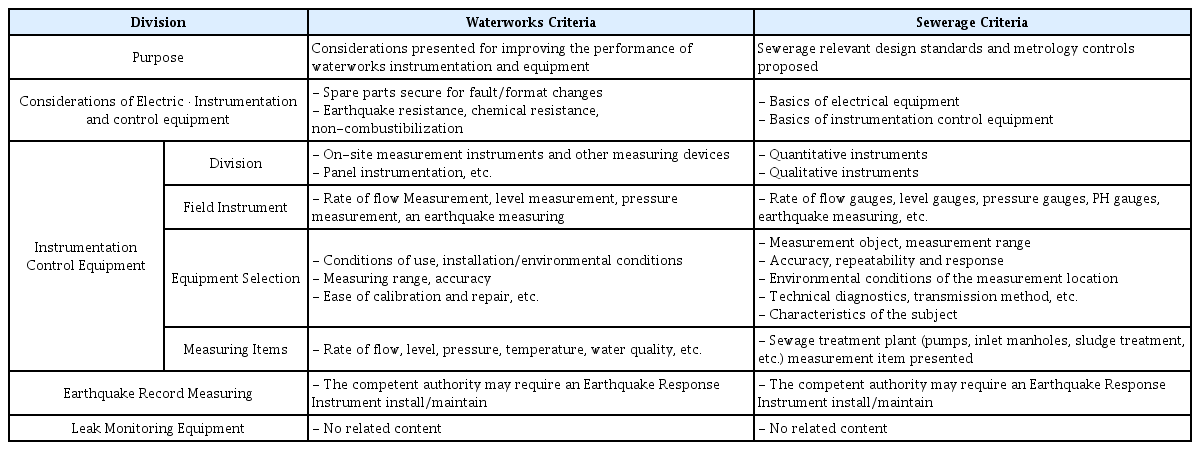
Measurement Criteria Comparative of Waterworks and Sewerage
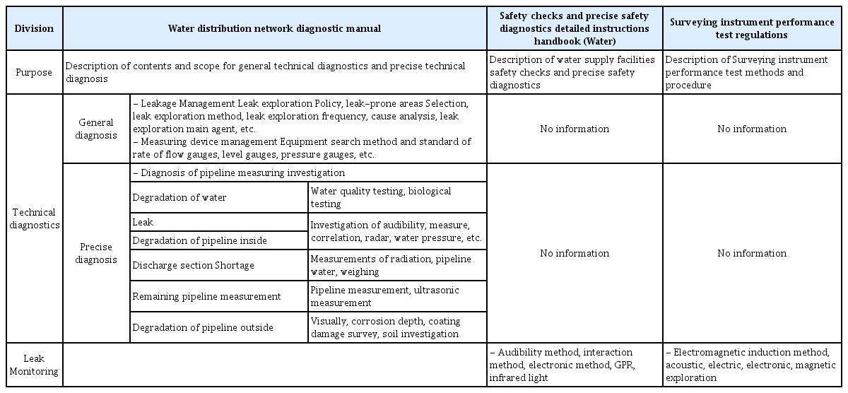
Water and Sewage Pipeline Diagnostic Criteria Comparison
3. 지반침하 대응을 위한 계측 및 탐사기술
3.1 지반침하 발생조건
지하시설물에서 발생하는 여러 가지 사건⋅사고 중 최근 가장 이슈화 되고 있는 ‘지반침하’ 발생조건을 분석하기 위해 정부 및 지자체에서 발표한 관련 자료들을 검토하였다. 국토부 ‘지반침하(함몰) 안전관리 매뉴얼’, 환경부 ‘하수관로 정밀조사 매뉴얼’, 서울시 ‘「석촌 지하차도 도로함몰」 관련 중간조사 및 대책방안’에서는 지반침하 발생조건을 비교적 상세하게 제시하고 있었으며, 그 외 자료에서는 발생원인 및 현황만 제시하고 있었다. 발생원인은 굴착공사, 누수, 연약지반침하, 지반동상, 역주변 펌핑, 지하수위변화, 지반 지지력상실, 토류벽 차수대책 부족 등 다양하게 제시하고 있었으며, 대부분 자료에서 상하수도관로를 지반침하와 원인으로 지목하고 있는 것을 알 수 있었다. 발생 현황은 발생규모에 대한 공통된 기준이 없어 동일연도에 발생한 지반침하라도 조사기관에 따라 발생횟수의 차이가 있었다. Table 3은 주요기관에서 발표한 지반침하 발생 조건, 발생원인 및 현황을 요약한 자료다.

Ground Subsidence Occurs Status and Conditions
정부 및 지자체에서 발표한 지반침하 발생원인 분석 자료를 검토한 결과 모든 자료들이 동일한 ‘발생조건’의 키워드를 포함하고 있는 것으로 나타났다. 이 점을 착안하여 국내 도심지에서 발생 가능한 지반침하 발생조건을 크게 3가지 1) 지하매설관로, 2) 굴착공사, 3) 지질조건 항목으로 분류하고, 각각 3개 세부항목으로 다시 분류하여 지반침하 발생조건을 제시하였다. 첫 번째, 지하매설관로에 기인한 지반침하 발생조건으로는 도심지지반침하 발생 원인으로 가장 크게 지목받고 있는 노후화가 진행된 상하수도관로, 외부 요인으로 볼 수 있는 대형공사 인접지역 관로, 그 밖에 노후된 통신, 가스관로 등 상하수도관로 이외의 지하매설관로의 파손 조건을 포함하였다. 두 번째, 굴착공사에 기인한 지반침하 발생조건은 공사중 유출 토사관리 미흡, 공사중 지하수위 변동 관리 미흡, 공사후 되메우기/다짐 불량으로 구분하였다. 마지막으로 지질조건영향은 지층자체가 충적층으로 형성되어 지반침하가 발생이 지속적으로 발생, 지반자체가 연약하여 압밀현상이 지속적으로 발생, 차량진동 또는 지진의 영향으로 인한 지반 지지력 상실을 포함하였다. Fig. 1은 지반침하 발생조건을 나타낸다.
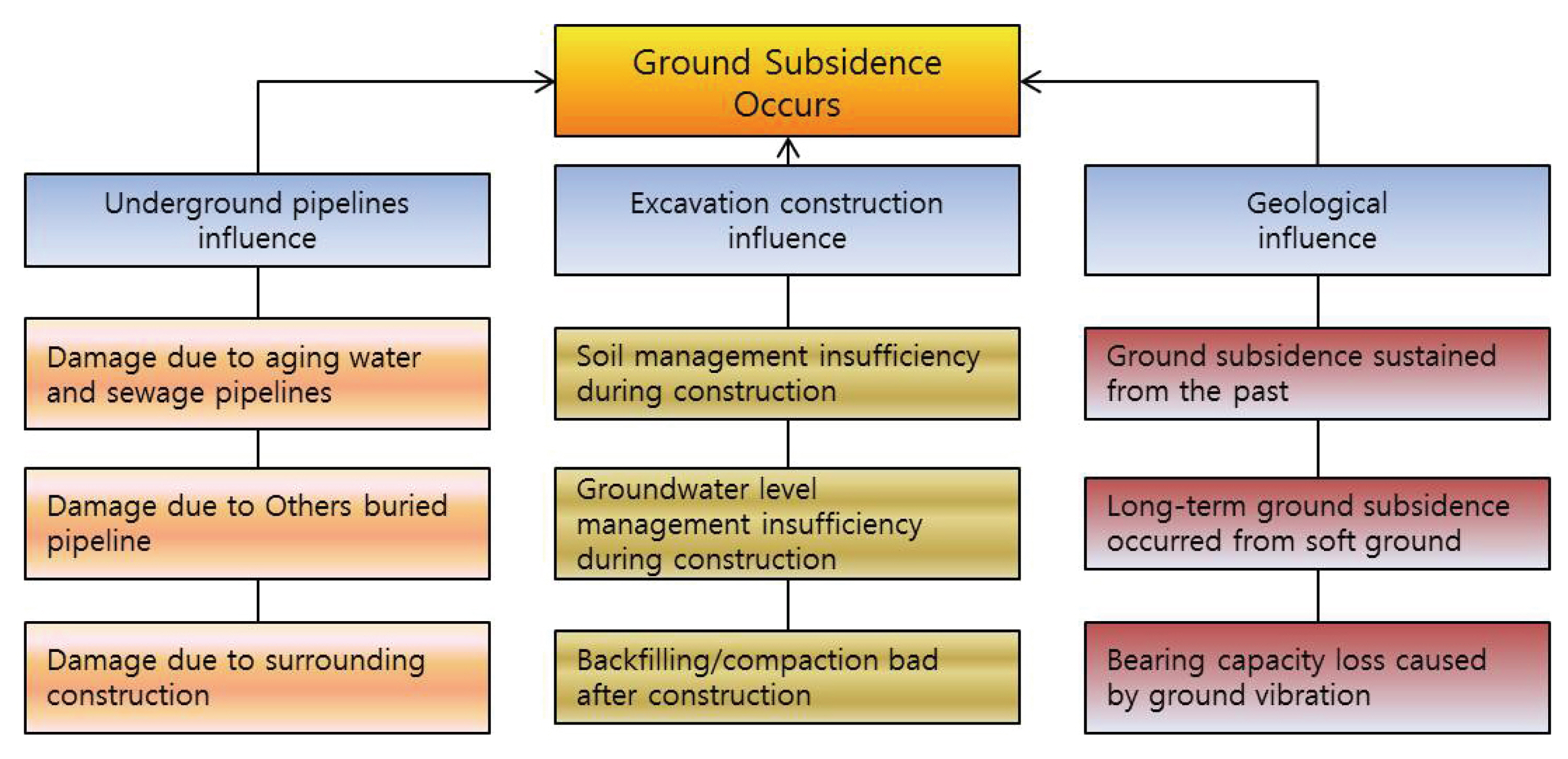
Ground Subsidence Occurring Condition
3.2 지반침하 대응방안
정부 및 지자체에서 발표한 자료에서는 상하수도관로가 도심지 지반침하를 유발하는 가장 큰 원인으로 지목하고 있으며, 이를 고려하여 상하수도관로에 모니터링 기술을 적용하는 것이 지반침하를 가장 효과적으로 대응할 수 있을 것이다. 모니터링 기술로는 관로 누수, 균열 등 결함 및 주변 공동 유무 등을 판단 할 수 있는 상수도 누수탐지 기술, 하수도 무인탐사기술, 하수관로 배면 공동 탐사기술이 적합하다고 판단되며, Fig. 2와 같이 대응 체계에 따라 선제적 및 긴급 대응 기술로 구분할 수 있다.

Ground Subsidence Response Technology
첫 번째, 선제적대응 기술은 관로 매설년도가 오래되어 누수로 인한 지반침하로 이어 질 수 있는 관로를 대상으로 적용하는 기술로 상수도관로의 경우 누수탐지를 위한 기술을 음향식 및 비음향식으로 나눌 수 있다. 음향식 계측장비는 상관식과 청음식장비 등으로, 비음향식 장비는 가스주입법, 지하침투레이더 장비 등으로 나눌 수 있으며 도심 소음 문제, 단수 및 교통차단 등 외부환경 조건을 충분히 고려한 후 누수 여부를 판단하고 복구하는 방법이다. 하수관로의 경우 무인 탐사장비를 이용한 이미지센싱 기술로 관로 누수와 직접적으로 연관된 이음부 결함, 연결관 접합부 결함, 파손여부 등을 고화질로 파악할 수 있는 탐사장비를 관로 내부에 직접 투입하여 지반침하를 야기시키는 누수여부를 판단 후 복구하는 방법이다.
두 번째, 긴급대응 기술은 과거에도 지반침하 이력이 있으며 현재도 위험지역으로 분류되는 지역, 미소한 지반침하가 지속적으로 발생하고 있는 지역 등 이미 지반침하로 이어질 수 있는 공동이 지층내부에 형성됐다고 판단되는 지역에 비파괴 검사 장비를 적용하여 공동존재 여부를 파악한 후 긴급대응하는 방법이다.
상하수도관로 주변 공동을 찾는 기술로는 도로 표층에서는 GPR, 전기비저항, 시추조사 등의 방법을 적용할 수 있으며, 또한 단수에 문제가 없는 하수관로의 경우 관로내부에 탐사장비를 직접 투입하는 충격탄성파방법, 공내 GPR, 방사능 밀도검층 방법 등도 활용할 수 있다.
4. 기술사양분석 및 최적 기술사양 도출
지반침하 대응 상하수도관로에 적용할 수 있는 기술들을 누수탐지, 관로탐사 및 관로배면 공동탐사 기술로 구분 하였다. 누수 및 관로 탐사 기술의 경우 상하수도관로 유지관리를 위해 활용되는 상용기술이 시장을 형성하고 있으며, 지반침하를 야기할 수 있는 누수지점 및 파손위치를 탐지하여 관리자가 의사결정을 할 수 있는 현장정보를 제공하는 것에 초점을 맞추고 있다. 관련 상용 기술의 종류가 다양한 만큼 일반적으로 사용하는 기술에 관해 기술 사양 분석을 실시하였다. 관로배면 공동탐사 기술의 경우 도심지의 지반침하에 직접 적용할 수 있는 기술은 없는 것으로 나타났으며, 토목, 국토개발, 자원탐사 등에서 활용하고 있는 기술을 기반으로 적용환경을 고려하여 응용⋅개발할 필요가 있으며, 기술사양 분석도 관련기술에 관해 실시하였다.
4.1 누수탐지기술
4.1.1 기술별 특징 분석
음향식 누수탐사 방법은 상관식 및 청음식으로 구분할 수 있으며 상관식 누수탐사는 배관의 매설깊이에 무관하게 탐사가 가능하며, 주변 소음의 영향도 비교적 영향이 적은 것이 장점으로 부각되었다. 단점으로는 적용 관경 및 관종의 제한이 있었으나 청음식 누수탐사의 문제점을 보완하여 적용할 수 있는 기술로 판단된다. 비음향식 누수탐사 방법으로 가스주입법은 배관에 물을 제거하고 가스를 주입해야하므로 물을 제거하지 않은 상황에서는 적용할 수 없으며 가스가 하수구나 다른 지점으로 흘러들어갈 위험성을 내포하고 있다. 레이더탐지(적외선탐지)의 경우 누수지점의 낮은 온도를 이용하는 방법으로 청음식과 달리 탐색지역에 제한은 없으나 밤, 낮, 비온 뒤 고인물과 구분하기 어려운 단점이 있다. 야간최소유량은 유수율을 산정하는 방법으로 야간누수량 단수조사의 경우 도심지 내 단수가 불가피하므로 사실상 적용이 불가능할 것으로 판단되며 누수감지케이블은 설치위치에 따라 정확한
누수지점의 탐지가 어렵고 주로 전기, 배관실 등 누수의 위험이 있는 실내 공간에 설치되므로 지하공간 매설환경에서는 적용하기 어려울 것으로 보인다. 기타기술의 경우 관로내부에 장치를 직접 투입하여 누수지점을 찾는 최신 기술로 국내에도 잘 알려진 A, B 기술이 있다. A 기술의 경우 볼 타입 형상으로 측정환경 조건에 대체로 적합한 것으로 나타났으나 최소구경 250 mm 이상, 유속 0.5 m/sec 이상, 적용구간 20 km 전후에 적용이 가능하지만 관로의 곡관부 또는 상하월부가 많은 관로 내부에는 장거리 구간 탐사시 위치 파악이 어려운 것으로 나타났다.
B기술의 경우 막대타입 형상으로, 도심지 도로 주변에 매설되어 있는 관경 300 mm이상의 모든 관종에 적용이 가능하나 관내부 결절 및 퇴적물이 존재하는 상황에서는 녹물을 발생시킬 우려가 있어 소구경의 단거리 또는 중거리 관로 구간에 선별적으로 적용 가능할 것으로 판단된다. Table 4는 누수탐사기술의 장⋅담점을 나타낸다.
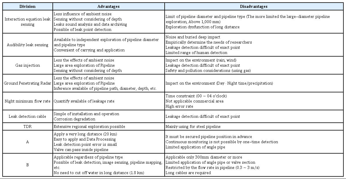
Compare Advantage and Disadvantage of the Leak Monitoring Technology
4.1.2 기술적용 환경 및 개선사항 도출
누수탐지 기술의 특성을 검토한 결과, 음향식 누수탐사에 비해 비음향식 누수탐사는 주변환경 및 시간적 제약요소가 큰 것으로 나타났다. 따라서 음향식 누수탐사기술과 최신 개발기술에 초점을 두어 기술적용 환경에 따른 각 기술의 성능을 검토하고 개선 사항을 도출하였다. Table 5는 누수탐사기술의 적용성을 나타낸다.

Technical Application Review of the Leak Sensing Technology
상수도관로 상시누수탐지를 위해 적용할 수 있는 기술을 검토한 결과 측정환경 조건에 대해서는 A기술이 가장 적합한 것으로 나타났으나 측정오차 및 재현성, 유지관리성, 측정범위에 대한 환경에서는 불리한 것으로 확인되었다. 청음식 누수탐지의 경우 인력에 의해 운영되는 특성상 상시탐지를 할 수 없으며 측정 오차가 많은 것으로 나타났다. 상관식 누수탐지의 경우 모든 환경에 대해 가장 적합한 것으로 나타났으나 대구경 관경, 관종에 따른 적용성 및 운영시간을 향상시킬 필요가 있는 것으로 판단된다.
4.2 관로탐사기술
4.2.1 기술별 특징 분석
CCTV에 의한 하수관로 검사장비는 고정형 CCTV방식 그리고 이동형 모바일 CCTV시스템으로 구분 할 수 있으며 장단점은 Table 6과 같다. 일반적으로 CCTV에 의한 하수관로 탐사장비는 사람이 들어갈 수 없는 하수관거 안에 CCTV를 탑재한 자주식 로봇차를 투입하여 촬영하는 장비를 일컬으며 모든 조종은 지상에서 장비차량에 장착된 모니터를 보며 확인, 동시 녹화할 수 있다. 처음에는 로봇차량에 원격제어 및 분석장비를 탑재하여 맨홀 위에서 측정하는 고정형 장비가 제안되기도 했으나 오직 맨홀 근처에서 측정만 가능하고 그 활용범위가 제한적이었다. 따라서 최신기술의 동향은 이동형 장비의 개발로 진화되었고 현재 미국과 유럽을 중심으로 각종 이동형 검사장비의 개발과 보급이 활발히 진행되고 있다.

Compare Advantage and Disadvantage of Image Sensing Technology
4.2.2 기술적용 환경 및 개선사항 도출
앞서 제시한 CCTV에 의한 하수관로 검사장비 기술분석을 토대로 최신 개발기술에 초점을 두어 기술적용 환경에 따른 요구성능과 적용성 검토결과를 Table 7에 나타내었다. 도심지의 교통흐름을 방해하지 않고 관로 내부의 건전도를 탐사하기 위해서는 고정형보다 이동형 검사장비를 활용하는 것이 효과적이라고 판단된다. 또한 이미지 센싱기술은 관로 내부의 오염도나 토사퇴적, 수위 등에 의한 장애요소가 항상 존재하므로 추가적인 측정장비(소나, 레이저스캐너 등)를 갖추는 것이 검사 정확도를 높일 수 있을 것이라 판단된다.
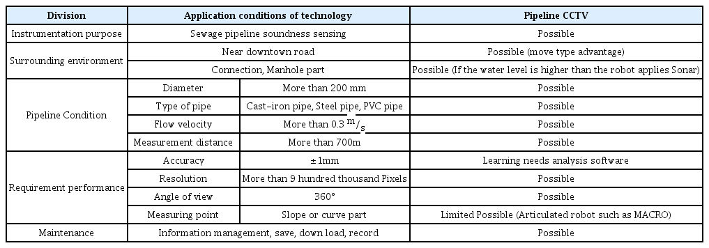
Application of Image Sensing Technology for Sewage Pipeline
4.3 관로배면 공동탐사 기술
4.3.1 기술별 특징 분석
배면공동의 위치 및 분포를 확인하기 위한 탐사기술을 원리에 따라 분류하면 충격탄성파, GPR, 전기비저항, 밀도검층 등이 사용되고 있다.
충격탄성파는 구조체에 탄성파를 발생시켜 반사체의 위치를 탐지하는 기법으로 신속하고 간편하게 측정이 가능한 장점을 가지고 있다. 특히 충격반향기법(IE)과 충격응답기법(IR)은 측정 원리가 비슷하여 동시측정이 가능하며 현재 해외에서는 콘크리트 슬래브 및 도로 등에 적용이 활발히 이루어지고 있다.
GPR 탐사는 전자기파를 이용하여 반사체에 대한 반사파를 연속적으로 획득하고, 이를 영상으로 나타나게 하여 반사체의 심도 및 위치를 파악할 수 있다. 전자파를 이용하기 때문에 도로 및 콘크리트 슬래브에서 손쉽게 사용 가능하고, 관로 및 공동의 위치를 바로 파악할 수 있는 장점을 가지고 있다. 그러나 주파수에 따라 분해능과 가탐심도가 반비례관계를 나타나게 되는데, 높은 분해능이 필요할 경우 가탐심도가 이종 물리탐사와 달리 낮은 것이 단점이다.
전기비저항탐사는 전극봉을 지면에 설치하고, 전류를 흘려보낸 후, 다른 전극의 전위차를 측정하므로 공동 및 함몰 지역에 대한 위치 및 범위까지 측정이 가능하다. 그러나 도로 및 콘크리트 슬래브 위에서 측정할 때는 접지저항이 높아 심부까지 전류가 흐르지 않아 측정결과를 신뢰할 수 없고, 전극봉을 설치하기 위해서는 천공을 해야하는 단점이 있다. 밀도검층의 경우 다른 탐사와 달리 탐사 비용이 높고, 정확한 자료를 획득할 수 있지만, 1개의 공에 대해서 확인이 가능하기 때문에 이종의 자료와 복합해석이 필요하다. 또한 검층을 통해서 공동의 위치에 대한 정보를 획득할 수 있지만 방사능 물질을 이용하기 때문에 지하수 오염 및 상하수도 오염에 대한 각별한 주의가 필요하다.
4.3.2 기술적용 환경 및 개선사항 도출
전기비저항 탐사 및 GPR은 넓은 지역에 대한 공동탐지를 할 수 있지만, 전기비저항은 콘크리트 상부 설치가 어려움에 따라 도심지 주변엔 적용이 적합하지 않을 것으로 판단된다. 또한 충격탄성파의 경우 실시간 모니터링이 불가능하고 넓은 범위의 측정이 어렵기 때문에 관로 배면공동을 탐지하기 위한 방법으로는 하수도 주변의 도로 및 콘크리트 주변 비파괴탐사가 가능하고, 관로 및 공동의 위치를 예측할 수 있는 GPR의 활용성이 좋을 것으로 보인다. 그러나 GPR 탐사는 도로하부에 철근이 매설된 경우, 전자파의 산란으로 그 하부에 대한 정보를 획득하기가 어려워 철근에 대한 노이즈 제거 필터링이 필요하다. 또한 높은 분해능이 요구될 경우 가탐심도가 낮아지므로 가탐심도 한계(5 m)에 대한 개선방안이 필요하다. Table 9는 관로배면 공동탐사 기술의 적용성을 분석한 결과를 나타낸다.

Compare Advantage and Disadvantage of Pipeline Rear Cavity Detection Technology
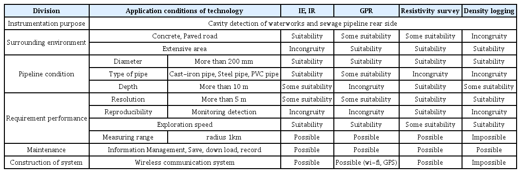
Application of Cavity Detection Technology for Sewage Pipeline
5. 결 론
최근 사회적으로 이슈화되고 있는 지반침하 대응을 위한 3가지 모니터링 기술(누수탐지기술, 하수관로 이미지센싱기술, 관로배면공동탐지기술)을 선정한 후 최적의 기술사양을 도출하기 위해 기술사양 검토 연구를 수행하였으며, 다음과 같은 결론을 얻을 수 있었다.
(1) 누수탐지 기술의 특성을 검토한 결과 측정환경 조건은 A기술이 가장 적합한 것으로 나타났으나 측정오차 및 재현성, 유지관리성, 측정범위에 대한 환경에서는 불리한 것으로 나타났다. 청음식 누수탐지의 경우 인력에 의해 운영되는 특성상 상시탐지를 할 수 없으며, 측정 오차도 큰 것으로 나타났다. 상관식 누수탐지 기술의 경우 모든 환경에 대해 가장 적합한 것으로 나타났으나 대구경 관경, 관종에 따른 적용성 및 운영시간을 향상시킬 필요가 있는 것으로 판단된다.
(2) 하수관로 이미지센싱 기술의 특성을 살펴본 결과 도심지의 교통흐름을 방해하지 않고 관로 내부의 건전도를 탐사하기 위해서는 이동형 검사장비를 활용해야 하는 것으로 나타났다. 또한, 이미지를 통한 검사기술은 관로 내부의 오염도나 토사퇴적, 수위 등 다양한 장애요소가 존재하므로 추가적인 측정장비(소나, 레이저 스캐너 등)를 갖추어 검사 정확도를 높일 필요가 있을 것으로 판단된다.
(3) 관로 배면공동 탐사기술의 특성을 살펴본 결과 하수도 주변의 도로 및 콘크리트 주변 비파괴탐사가 가능하고, 관종 및 관경을 예측할 수 있는 GPR의 활용성이 가장 우수한 것으로 판단된다. 하지만 GPR 탐사는 금속관 종일 경우, 전자파의 산란으로 그 하부에 대한 정보를 획득하기 어려운 점이 있으므로 철근에 대한 노이즈 제거 필터링이 필요하며, 높은 분해능이 요구될 경우 가탐심도가 낮아지므로 가탐심도 한계(5 m)에 대한 개선방안이 필요할 것으로 판단된다.
Acknowledgements
본 연구는 미래창조과학부 및 국가과학기술연구회의 융합 연구사업의 일환으로 수행하였음. [융합연구단-14-2-ETRI, 사물인터넷(IoT) 기반 도시 지하매설물 모니터링 및 관리시스템 기술 개발]